Dead Load on Composite
The procedure to distribute the superimposed dead load on composite and on supplemental based on tributary fraction is: First, the uniform surface load is multiplied by the overall width of the bridge to obtain the total dead load acting on the bridge. Then, a continuous beam analysis is performed to compute moments and shears at tenth points at each span. The default proportionate share of moment and shear distributed to each beam is:
where:
DL - Comp Trib Frac = Tributary fraction for dead load on composite
Btrib = Tributary width of beam under consideration
Overall Width = Out-to-out width of the bridge.
Pedestrian/Sidewalk Loads
The pedestrian or sidewalk load effects are first computed for the entire bridge based on composite action and then distributed to each girder as a ratio of the tributary width fraction.
Live Load
The axle load distribution factor can be computed by the program or entered manually by the user. To manually input the axle load distribution factor, go to the Analysis tab and click the Analysis Factors button. Then, on the Distribution Factors tab, select the Manual option and input the desired values in the fields for moment and shear for the appropriate group. The axle load distribution factor is half the wheel load distribution factor.
| Case | D.F. Calculation | AASHTO LFD Reference |
|---|---|---|
| Number of beams = any type of selection | D.F. = (number of lanes) (lane load reduction factor) | Art. 312 |
| Interior Longitudinal Stringer, one lane | D.F. = S/7 or as simple span* if S exceeds 10 ft | Table 3.23.1 |
| Interior Longitudinal Stringer, 2 or more lanes | D.F. = S/5.5 or as simple span* if S exceeds 14 feet | Table 3.23.1 |
| Exterior Longitudinal Stringer | D.F. = As simple span*. | Art. 3.23.2.3.1.2 |
| Interior Spread Box Girder, Interior Open Box Beam | D.F. = AASHTO LFD Eq. 3-33 | Art. 3.28.1 |
| Exterior Spread Box Girder, Exterior Open Box Beam | D.F. = As simple span* and not less than 2 x NL/Nb | Art. 3.28.2 |
| Multi-beams | D.F. = S/D (see below for values of K used) | Art. 3.23.4.3 |
| Longitudinal Stringer | AASHTO Girder Stringer, Rectangular Stringer, Special Longitudinal Stringer |
| Spread Box Beam | Spread Box Girder |
| Multi-Beam |
Adjacent Box Beam, K = 1.0 Channel Beam, K = 2.2 Double Tee, K = 2.2 Non-voided Rect. Beam, K = 0.7 Rect. Beam w/ Round Voids, K = 0.8 |
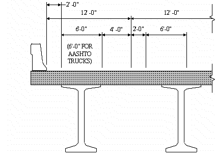
The figure below illustrates the model for determining the distribution factor for an exterior beam using the simple span (i.e., lever rule) assumption explained above. The first wheel is placed at a distance from the curb equal to 2 ft.
If using loading Group IA, the distribution factor is calculated for only one lane. As specified in Art. 3.5.1, Group IA only needs to be considered for loads less than H20.